


Thursday, 15 December 2016
Tuesday, 22 November 2016
Submarine communications cable
Submarine communications cable
A submarine communications cable is a cable laid on the sea bedbetween land-based stations to carry telecommunication signals across stretches of ocean. The first submarine communications cables, laid in the 1850s, carried telegraphy traffic. Subsequent generations of cables carried telephone traffic, then data communications traffic. Modern cables use optical fiber technology to carry digital data, which includes telephone, Internet and private data traffic.
Modern cables are typically 69 millimetres (2.7 in) in diameter and weigh around 10 kilograms per metre (7 lb/ft), although thinner and lighter cables are used for deep-water sections As of 2010, submarine cables link all the world's continents except Antarctica.
Early history: telegraph and coaxial cables
Trials
After William Cooke and Charles Wheatstone had introduced their working telegraph in 1839, the idea of a submarine line across the Atlantic Ocean began to be thought of as a possible triumph of the future. Samuel Morse proclaimed his faith in it as early as 1840, and in 1842, he submerged a wire, insulated with tarred hemp and India rubber, in the water of New York Harbor, and telegraphed through it. The following autumn, Wheatstone performed a similar experiment in Swansea Bay. A good insulator to cover the wire and prevent the electric current from leaking into the water was necessary for the success of a long submarine line. India rubber had been tried by Moritz von Jacobi, the Prussian electrical engineer, as far back as the early 19th century.
https://www.youtube.com/my_videos?o=U
https://www.youtube.com/my_videos?o=U
Another insulating gum which could be melted by heat and readily applied to wire made its appearance in 1842. Gutta-percha, the adhesive juice of the Palaquium gutta tree, was introduced to Europe by William Montgomerie, a Scottishsurgeon in the service of the British East India Company.:26–27 Twenty years earlier, he had seen whips made of it inSingapore, and he believed that it would be useful in the fabrication of surgical apparatuses. Michael Faraday and Wheatstone soon discovered the merits of gutta-percha as an insulator, and in 1845, the latter suggested that it should be employed to cover the wire which was proposed to be laid from Dover to Calais. It was tried on a wire laid across the Rhinebetween Deutz and Cologne. In 1849, C.V. Walker, electrician to the South Eastern Railway, submerged a two-mile wire coated with gutta-percha off the coast from Folkestone, which was tested successfully.
First commercial cables

Having earlier obtained a concession from the French Government, in August 1850John Watkins Brett's Anglo-French Telegraph Company laid the first line across theEnglish Channel, using the converted tug Goliath. It was simply a copper wire coated with gutta-percha, without any other protection, and was not successful.The experiment served to secure renewal of the concession, and in September 1851, a protected core, or true, cable was laid by the reconstituted Submarine Telegraph Company from a government hulk, the Blazer, which was towed across the Channel.
In 1853 further successful cables were laid, linking Great Britain with Ireland,Belgium and the Netherlands, and crossing The Belts in Denmark.The British & Irish Magnetic Telegraph Company completed the first successful Irish link on May 23 between Portpatrick and Donaghadee using the collier William Hutt.The same ship was used for the link from Dover to Ostend in Belgium, by the Submarine Telegraph Company.:192–193 Meanwhile, the Electric & International Telegraph Company completed two cables across the North Sea, from Orford Nessto Scheveningen, The Netherlands. They were laid by the Monarch, a paddle steamer which later became the first vessel with permanent cable-laying equipment.https://www.youtube.com/my_videos?o=U
Transatlantic telegraph cable
Main article: Transatlantic telegraph cable
The first attempt at laying a transatlantic telegraph cable was promoted by Cyrus West Field, who persuaded British industrialists to fund and lay one in 1858. However, the technology of the day was not capable of supporting the project; it was plagued with problems from the outset, and was in operation for only a month. Subsequent attempts in 1865 and 1866 with the world's largest steamship, the SS Great Eastern, used a more advanced technology and produced the first successful transatlantic cable. The Great Eastern later went on to lay the first cable reaching to India from Aden, Yemen, in 1870.
British dominance of early cable
From the 1850s until 1911, British submarine cable systems dominated the most important market, the North Atlantic Ocean. The British had both supply side and demand side advantages. In terms of supply, Britain had entrepreneurs willing to put forth enormous amounts of capital necessary to build, lay and maintain these cables. In terms of demand, Britain's vast colonial empire led to business for the cable companies from news agencies, trading and shipping companies, and the British government. Many of Britain's colonies had significant populations of European settlers, making news about them of interest to the general public in the home country.
British officials believed that depending on telegraph lines that passed through non-British territory posed a security risk, as lines could be cut and messages could be interrupted during wartime. They sought the creation of a worldwide network within the empire, which became known as the All Red Line, and conversely prepared strategies to quickly interrupt enemy communications. Britain's very first action after declaring war on Germany in World War I was to have the cable ship Alert(not the CS Telconia as frequently reported) cut the five cables linking Germany with France, Spain and the Azores, and through them, North America. Thereafter the only way Germany could communicate was by wireless, and that meant thatRoom 40 could listen in.
The submarine cables were an economic boon to trading companies because owners of ships could communicate with captains when they reached their destination on the other side of the ocean and even give directions as to where to go next to pick up more cargo based on reported pricing and supply information. The British government had obvious uses for the cables in maintaining administrative communications with governors throughout its empire, as well as in engaging other nations diplomatically and communicating with its military units in wartime. The geographic location of British territory was also an advantage as it included both Ireland on the east side of the Atlantic ocean and Newfoundland in North America on the west side, making for the shortest route across the ocean, which reduced costs significantly.
A few facts put this dominance of the industry in perspective. In 1896, there were thirty cable laying ships in the world and twenty-four of them were owned by British companies. In 1892, British companies owned and operated two-thirds of the world's cables and by 1923, their share was still 42.7 percent. During World War I, Britain's telegraph communications were almost completely uninterrupted, while it was able to quickly cut Germany's cables worldwide.
Cable to India, Singapore, Far East and Australia

Throughout the 1860s and 70's, British cable expanded eastward, into the Mediterranean Sea and the Indian Ocean. An 1863 cable toBombay, India (now Mumbai) provided a crucial link to Saudi Arabia.In 1870, Bombay was linked to London via submarine cable in a combined operation by four cable companies, at the behest of the British Government. In 1872, these four companies were combined to form the mammoth globespanning Eastern Telegraph Company, owned by John Pender. A spin-off from Eastern Telegraph Company was a second sister company, the Eastern Extension, China and Australasia Telegraph Company, commonly known simply as "the Extension". In 1872, Australia was linked by cable to Bombay via Singapore and China and in 1876, the cable linked the British Empire from London to New Zealand.https://www.youtube.com/my_videos?o=U
Submarine cables across the Pacific
The first trans-pacific cables were completed in 1902–03, linking the US mainland to Hawaii in 1902 and Guam to the Philippines in 1903. Canada, Australia, New Zealand and Fiji were also linked in 1902 with the trans-Pacific segment of the All Red Line.
88 years later, the North Pacific Cable system was the first regenerative (repeatered) system to completely cross the Pacific from the US mainland to Japan. The US portion of NPC was manufactured in Portland, Oregon, from 1989 to 1991 at STC Submarine Systems, and later Alcatel Submarine Networks. The system was laid by Cable & Wireless Marine on the CSCable Venture in 1991.
Construction
Transatlantic cables of the 19th century consisted of an outer layer of iron and later steel wire, wrapping India rubber, wrapping gutta-percha, which surrounded a multi-stranded copper wire at the core. The portions closest to each shore landing had additional protective armor wires. Gutta-percha, a natural polymer similar to rubber, had nearly ideal properties for insulating submarine cables, with the exception of a rather high dielectric constant which made cable capacitance high. Gutta-percha was not replaced as a cable insulation until polyethylene was introduced in the 1930s. In the 1920s, the American military experimented with rubber-insulated cables as an alternative to gutta-percha, since American interests controlled significant supplies of rubber but no gutta-percha manufacturers.
Bandwidth problems
Early long-distance submarine telegraph cables exhibited formidable electrical problems. Unlike modern cables, the technology of the 19th century did not allow for in-line repeater amplifiers in the cable. Large voltages were used to attempt to overcome the electrical resistance of their tremendous length but the cables' distributed capacitance and inductancecombined to distort the telegraph pulses in the line, reducing the cable's bandwidth, severely limiting the data rate for telegraph operation to 10–12 words per minute.
As early as 1823, Francis Ronalds had observed that electric signals were retarded in passing through an insulated wire or core laid underground, and the same effect was noticed by Latimer Clark (1853) on cores immersed in water, and particularly on the lengthy cable between England and The Hague. Michael Faraday showed that the effect was caused by capacitance between the wire and the earth (or water) surrounding it. Faraday had noticed that when a wire is charged from a battery (for example when pressing a telegraph key), the electric charge in the wire induces an opposite charge in the water as it travels along. In 1831, Faraday described this effect in what is now referred to as Faraday's law of induction. As the two charges attract each other, the exciting charge is retarded. The core acts as a capacitor distributed along the length of the cable which, coupled with the resistance and inductance of the cable, limits the speed at which asignal travels through the conductor of the cable.
Early cable designs failed to analyze these effects correctly. Famously, E.O.W. Whitehouse had dismissed the problems and insisted that a transatlantic cable was feasible. When he subsequently became electrician of the Atlantic Telegraph Company, he became involved in a public dispute with William Thomson. Whitehouse believed that, with enough voltage, any cable could be driven. Because of the excessive voltages recommended by Whitehouse, Cyrus West Field's first transatlantic cable never worked reliably, and eventually short circuited to the ocean when Whitehouse increased the voltage beyond the cable design limit.
Thomson designed a complex electric-field generator that minimized current by resonating the cable, and a sensitive light-beam mirror galvanometer for detecting the faint telegraph signals. Thomson became wealthy on the royalties of these, and several related inventions. Thomson was elevated to Lord Kelvin for his contributions in this area, chiefly an accuratemathematical model of the cable, which permitted design of the equipment for accurate telegraphy. The effects ofatmospheric electricity and the geomagnetic field on submarine cables also motivated many of the early polar expeditions.
Thomson had produced a mathematical analysis of propagation of electrical signals into telegraph cables based on their capacitance and resistance, but since long submarine cables operated at slow rates, he did not include the effects of inductance. By the 1890s, Oliver Heaviside had produced the modern general form of the telegrapher's equations, which included the effects of inductance and which were essential to extending the theory of transmission lines to higherfrequencies required for high-speed data and voice.
Transatlantic telephony

While laying a transatlantic telephone cable was seriously considered from the 1920s, the technology required for economically feasible telecommunications was not developed until the 1940s. A first attempt to lay a pupinized telephone cable failed in the early 1930s due to the Great Depression.
In 1942, Siemens Brothers of New Charlton, London in conjunction with the United Kingdom National Physical Laboratory, adapted submarine communications cable technology to create the world's first submarine oil pipeline in Operation Pluto duringWorld War II.
TAT-1 (Transatlantic No. 1) was the first transatlantic telephone cable system. Between 1955 and 1956, cable was laid between Gallanach Bay, near Oban, Scotland and Clarenville, Newfoundland and Labrador. It was inaugurated on September 25, 1956, initially carrying 36 telephone channels.https://www.youtube.com/my_videos?o=U
In the 1960s, transoceanic cables were coaxial cables that transmitted frequency-multiplexed voiceband signals. A high voltage direct current on the inner conductor powered repeaters (two-way amplifiers placed at intervals along the cable). The first-generation repeaters remain among the most reliable vacuum tube amplifiers ever designed. Later ones were transistorized. Many of these cables are still usable, but have been abandoned because their capacity is too small to be commercially viable. Some have been used as scientific instruments to measure earthquake waves and other geomagnetic events.
Modern history
Optical telephone cables

In the 1980s, fiber optic cables were developed. The first transatlantic telephone cable to use optical fiber was TAT-8, which went into operation in 1988. A fiber-optic cable comprises multiple pairs of fibers. Each pair has one fiber in each direction. TAT-8 had two operational pairs and one backup pair.
Modern optical fiber repeaters use a solid-state optical amplifier, usually an Erbium-doped fiber amplifier. Each repeater contains separate equipment for each fiber. These comprise signal reforming, error measurement and controls. A solid-state laser dispatches the signal into the next length of fiber. The solid-state laser excites a short length of doped fiber that itself acts as a laser amplifier. As the light passes through the fiber, it is amplified. This system also permits wavelength-division multiplexing, which dramatically increases the capacity of the fiber.
Repeaters are powered by a constant direct current passed down the conductor near the center of the cable, so all repeaters in a cable are in series. Power feed equipment is installed at the terminal stations. Typically both ends share the current generation with one end providing a positive voltage and the other a negative voltage. A virtual earth point exists roughly halfway along the cable under normal operation. The amplifiers or repeaters derive their power from the potential difference across them.
The optic fiber used in undersea cables is chosen for its exceptional clarity, permitting runs of more than 100 kilometers between repeaters to minimize the number of amplifiers and the distortion they cause.
The rising demand for these fiber-optic cables outpaced the capacity of providers such as AT&T. Having to shift traffic to satellites resulted in poorer quality signals. To address this issue, AT&T had to improve its cable laying abilities. It invested $100 million in producing two specialized fiber-optic cable laying vessels. These included laboratories in the ships for splicing cable and testing its electrical properties. Such field monitoring is important because the glass of fiber-optic cable is less malleable than the copper cable that had been formerly used. The ships are equipped with thrusts that increase maneuverability. This capability is important because fiber-optic cable must be laid straight from the stern (another factor copper cable laying ships did not have to contend with).
Originally, submarine cables were simple point-to-point connections. With the development of submarine branching units(SBUs), more than one destination could be served by a single cable system. Modern cable systems now usually have their fibers arranged in a self-healing ring to increase their redundancy, with the submarine sections following different paths on the ocean floor. One driver for this development was that the capacity of cable systems had become so large that it was not possible to completely back-up a cable system with satellite capacity, so it became necessary to provide sufficient terrestrial back-up capability. Not all telecommunications organizations wish to take advantage of this capability, so modern cable systems may have dual landing points in some countries (where back-up capability is required) and only single landing points in other countries where back-up capability is either not required, the capacity to the country is small enough to be backed up by other means, or having back-up is regarded as too expensive.https://www.youtube.com/my_videos?o=U
A further redundant-path development over and above the self-healing rings approach is the "Mesh Network" whereby fast switching equipment is used to transfer services between network paths with little to no effect on higher-level protocols if a path becomes inoperable. As more paths become available to use between two points, the less likely it is that one or two simultaneous failures will prevent end-to-end service.
As of 2012, operators had "successfully demonstrated long-term, error-free transmission at 100 Gaps across Atlantic Ocean" routes of up to 6,000 km (3,700 mi), meaning a typical cable can move tens of terabits per second overseas. Speeds improved rapidly in the last few years, with 40 G bit/s having been offered on that route only three years earlier in August 2009.
Switching and all-by-sea routing commonly increases the distance and thus the round trip latency by more than 50%. For example, the round trip delay (RTD) or latency of the fastest transatlantic connections is under 60 ms, close to the theoretical maximum for an all-sea route. While in theory, a great circle route between London and New York City is only 5,600 km (3,500 mi), this requires several land masses (Ireland, Newfoundland, Prince Edward Island and the isthmus connecting New Brunswick to Nova Scotia) to be traversed, as well as the extremely tidal Bay of Fundy and a land route along Massachusetts' north shore from Gloucester to Boston and through fairly built up areas to Manhattan itself. In theory, using this partly land route could result in round trip times below 40 ms, not counting switching (which is the speed of light minimum). Along routes with less land in the way, speeds can approach speed of light minimums in the long term.
Importance of submarine cables
As of 2006, overseas satellite links accounted for only 1 percent of international traffic, while the remainder was carried by undersea cable. The reliability of submarine cables is high, especially when (as noted above) multiple paths are available in the event of a cable break. Also, the total carrying capacity of submarine cables is in the terabits per second, while satellites typically offer only 1000 megabits per second and display higher latency. However, a typical multi-terabit, transoceanic submarine cable system costs several hundred million dollars to construct.
https://www.youtube.com/my_videos?o=U
https://www.youtube.com/my_videos?o=U
As a result of these cables' cost and usefulness, they are highly valued not only by the corporations building and operating them for profit, but also by national governments. For instance, the Australian government considers its submarine cable systems to be "vital to the national economy". Accordingly, the Australian Communications and Media Authority (ACMA) has created protection zones that restrict activities that could potentially damage cables linking Australia to the rest of the world. The ACME also regulates all projects to install new submarine cables.
Investment in and financing of submarine cables
Almost all fiber optic cables from TAT-8 in 1988 until approximately 1997 were constructed by "consortia" of operators. For example, TAT-8 counted 35 participants including most major international carriers at the time such as AT&T Corporation. Two privately financed, non-consortium cables were constructed in the late 1990s, which preceded a massive, speculative rush to construct privately financed cables that peaked in more than $22 billion worth of investment between 1999 and 2001. This was followed by the bankruptcy and reorganization of cable operators such as Global Crossing, 360networks, FLAG, Worldcom, and Asia Global Crossing.
There has been an increasing tendency in recent years to expand submarine cable capacity in the Pacific Ocean (the previous bias always having been to lay communications cable across the Atlantic Ocean which separates the United States and Europe). For example, between 1998 and 2003, approximately 70% of undersea fiber-optic cable was laid in the Pacific. This is in part a response to the emerging significance of Asian markets in the global economy.

Although much of the investment in submarine cables has been directed toward developed markets such as the transatlantic and transpacific routes, in recent years there has been an increased effort to expand the submarine cable network to serve the developing world. For instance, in July 2009, an underwater fiber optic cable line plugged East Africa into the broader Internet. The company that provided this new cable was SEACOM, which is 75% owned by Africans. The project was delayed by a month due to increased piracy along the coast.
https://www.youtube.com/my_videos?o=U
https://www.youtube.com/my_videos?o=U
Antarctica
Antarctica is the only continent yet to be reached by a submarine telecommunications cable. All phone, video, and e-mail traffic must be relayed to the rest of the world via satellite, which is still quite unreliable. Bases on the continent itself are able to communicate with one another via radio, but this is only a local network. To be a viable alternative, a fiber-optic cable would have to be able to withstand temperatures of −80˚ C as well as massive strain from ice flowing up to 10 meters per year. Thus, plugging into the larger Internet backbone with the high bandwidth afforded by fiber-optic cable is still an as yet infeasible economic and technical challenge in the Antarctic.
Cable repair
Cables can be broken by fishing trawlers, anchors, earthquakes, turbidity currents, and even shark bites. Based on surveying breaks in the Atlantic Ocean and the Caribbean Sea, it was found that between 1959 and 1996, fewer than 9% were due to natural events. In response to this threat to the communications network, the practice of cable burial has developed. The average incidence of cable faults was 3.7 per 1,000 km (620 mi) per year from 1959 to 1979. That rate was reduced to 0.44 faults per 1000 km per year after 1985, due to widespread burial of cable starting in 1980. Still, cable breaks are by no means a thing of the past, with more than 50 repairs a year in the Atlantic alone, and significant breaks in 2006, 2008, and 2009.
The propensity for fishing trawler nets to cause cable faults may well have been exploited during the Cold War. For example, in February 1959, a series of 12 breaks occurred in five American trans-Atlantic communications cables. In response, a United States naval vessel, the U.S.S. Roy O. Hale, detained and investigated the Soviet trawler Novorosiysk. A review of the ship's log indicated it had been in the region of each of the cables when they broke. Broken sections of cable were also found on the deck of the Novorosiysk. It appeared that the cables had been dragged along by the ship's nets, and then cut once they were pulled up onto the deck to release the nets. The Soviet Union's stance on the investigation was that it was unjustified, but the United States cited the Convention for the Protection of Submarine Telegraph Cables of 1884 to which Russia had signed (prior to the formation of the Soviet Union) as evidence of violation of international protocol.
Shore stations can locate a break in a cable by electrical measurements, such as through spread-spectrum time-domain reflectometry (SSTDR). SSTDR is a type of time-domain reflectometry that can be used in live environments very quickly. Presently, SSTDR can collect a complete data set in 20 ms. Spread spectrum signals are sent down the wire and then the reflected signal is observed. It is then correlated with the copy of the sent signal and algorithms are applied to the shape and timing of the signals to locate the break.
A cable repair ship will be sent to the location to drop a marker buoy near the break. Several types of grapples are used depending on the situation. If the sea bed in question is sandy, a grapple with rigid prongs is used to plough under the surface and catch the cable. If the cable is on a rocky sea surface, the grapple is more flexible, with hooks along its length so that it can adjust to the changing surface. In especially deep water, the cable may not be strong enough to lift as a single unit, so a special grapple that cuts the cable soon after it has been hooked is used and only one length of cable is brought to the surface at a time, whereupon a new section is spliced in. The repaired cable is longer than the original, so the excess is deliberately laid in a 'U' shape on the seabed. A submersible can be used to repair cables that lie in shallower waters.
A number of ports near important cable routes became homes to specialised cable repair ships. Halifax, Nova Scotia was home to a half dozen such vessels for most of the 20th century including long-lived vessels such as the CS Cyrus West Field, CS Minia and CS Mackay-Bennett. The latter two were contracted to recover victims from the sinking of the RMSTitanic. The crews of these vessels developed many new techniques and devices to repair and improve cable laying, such as the "plough".
Intelligence gathering
Underwater cables, which cannot be kept under constant surveillance, have tempted intelligence-gathering organizations since the late 19th century. Frequently at the beginning of wars, nations have cut the cables of the other sides to redirect the information flow into cables that were being monitored. The most ambitious efforts occurred in World War I, when British and German forces systematically attempted to destroy the others' worldwide communications systems by cutting their cables with surface ships or submarines. During the Cold War, the United States Navy and National Security Agency(NSA) succeeded in placing wire taps on Soviet underwater communication lines in Operation Ivy Bells.
Environmental impact
The main point of interaction of cables with marine life is in the benthic zone of the oceans where the majority of cable lies. Recent studies (in 2003 and 2006) have indicated that cables pose minimal impacts on life in these environments. In sampling sediment cores around cables and in areas removed from cables, there were few statistically significant differences in organism diversity or abundance. The main difference was that the cables provided an attachment point for anemones that typically could not grow in soft sediment areas. Data from 1877 to 1955 showed a total of 16 cable faults caused by the entanglement of various whales. Such deadly entanglements have entirely ceased with improved techniques for placement of modern coaxial and fiber-optic cables which have less tendency to self-coil when lying on the seabed.
Notable events
The Newfoundland earthquake of 1929 broke a series of trans-Atlantic cables by triggering a massive undersea mudslide. The sequence of breaks helped scientists chart the progress of the mudslide.
In July 2005, a portion of the SEA-ME-WE 3 submarine cable located 35 kilometres (22 mi) south of Karachi that providedPakistan's major outer communications became defective, disrupting almost all of Pakistan's communications with the rest of the world, and affecting approximately 10 million Internet users.
On 26 December 2006, the 2006 Hengchun earthquake rendered numerous cables between Taiwan and Philippinesinoperable.
In March 2007, pirates stole an 11-kilometre (7 mi) section of the T-V-H submarine cable that connected Thailand, Vietnam, and Hong Kong, affecting Vietnam's Internet users with far slower speeds. The thieves attempted to sell the 100 tons of cable as scrap.
The 2008 submarine cable disruption was a series of cable outages, two of the three Suez Canal cables, two disruptions in the Persian Gulf, and one in Malaysia. It caused massive communications disruptions to India and the Middle East.
In April 2010, the undersea cable SEA-ME-WE 4 was under an outage. The South East Asia–Middle East–Western Europe 4 (SEA-ME-WE 4) submarine communications cable system, which connects South East Asia and Europe, was reportedly cut in three places, off Palermo, Italy.
The 2011 Tōhoku earthquake and tsunami damaged a number of undersea cables that make landings in Japan, including.
- APCN-2, an intra-Asian cable that forms a ring linking China, Hong Kong, Japan, the Republic of Korea, Malaysia, the Philippines, Singapore, and Taiwan
- Pacific Crossing West and Pacific Crossing North
- Segments of the East Asia Crossing network (reported by PacNet)
- A segment of the Japan-U.S. Cable Network (reported by Korea Telecom)
- PC-1 submarine cable system (reported by NTT)
In February 2012, breaks in the EASSy and TEAMS cables disconnected about half of the networks in Kenya and Uganda from the global Internet.
In March 2013, the SEA-ME-WE-4 connection from France to Singapore was cut by divers near Egypt.
In November 2014 the SEA-ME-WE 3 stopped all traffic from Perth, Australia to Singapore due to an unknown cable fault.
https://www.youtube.com/my_videos?o=U
https://www.youtube.com/my_videos?o=U
Monday, 6 July 2015
Optical fibers
Optical fiber

An optical fiber (or optical fibre) is a flexible, transparent fiber made by drawingglass (silica) or plastic to a diameter slightly thicker than that of a human hair.Optical fibers are used most often as a means to transmit light between the two ends of the fiber and find wide usage in fiber-optic communications, where they permit transmission over longer distances and at higher bandwidths (data rates) than wire cables. Fibers are used instead of metal wires because signals travel along them with lesser amounts of loss; in addition, fibers are also immune toelectromagnetic interference, a problem which metal wires suffer from excessively. Fibers are also used for illumination, and are wrapped in bundles so that they may be used to carry images, thus allowing viewing in confined spaces, as in the case of a fiberscope. Specially designed fibers are also used for a variety of other applications, some of them being fiber optic sensors and fiber lasers.
Optical fibers typically include a transparent core surrounded by a transparentcladding material with a lower index of refraction. Light is kept in the core by the phenomenon of total internal reflection which causes the fiber to act as awaveguide. Fibers that support many propagation paths or transverse modes are called multi-mode fibers (MMF), while those that support a single mode are calledsingle-mode fibers (SMF). Multi-mode fibers generally have a wider core diameter and are used for short-distance communication links and for applications where high power must be transmitted. Single-mode fibers are used for most communication links longer than 1,000 meters (3,300 ft).
An important aspect of a fiber optic communication is that of extension of the fiber optic cables such that the losses brought about by joining two different cables is kept to a minimum. Joining lengths of optical fiber often proves to be more complex than joining electrical wire or cable and involves the carefully cleaving of the fibers, perfect alignment of the fiber cores and the splicing of these aligned fiber cores. For applications that demand a permanent connection a mechanical splicewhich holds the ends of the fibers together mechanically could be used or a fusion splice that uses heat to fuse the ends of the fibers together could be used. Temporary or semi-permanent connections are made by means of specializedoptical fiber connectors.
The field of applied science and engineering concerned with the design and application of optical fibers is known as fiber optics.
History
,1884.JPG)
Guiding of light by refraction, the principle that makes fiber optics possible, was first demonstrated by Daniel Colladon and Jacques Babinet in Paris in the early 1840s.John Tyndall included a demonstration of it in his public lectures in London, 12 years later. Tyndall also wrote about the property of total internal reflection in an introductory book about the nature of light in 1870:
Unpigmented human hairs have also been shown to act as an optical fiber.
Practical applications, such as close internal illumination during dentistry, appeared early in the twentieth century. Image transmission through tubes was demonstrated independently by the radio experimenter Clarence Hansell and the television pioneer John Logie Baird in the 1920s. The principle was first used for internal medical examinations by Heinrich Lamm in the following decade. Modern optical fibers, where the glass fiber is coated with a transparent cladding to offer a more suitable refractive index, appeared later in the decade. Development then focused on fiber bundles for image transmission. Harold Hopkins and Narinder Singh Kapany at Imperial College in London achieved low-loss light transmission through a 75 cm long bundle which combined several thousand fibers. Their article titled "A flexible fibrescope, using static scanning" was published in the journal Nature in 1954. The first fiber optic semi-flexible gastroscope was patented by Basil Hirschowitz, C. Wilbur Peters, and Lawrence E. Curtiss, researchers at theUniversity of Michigan, in 1956. In the process of developing the gastroscope, Curtiss produced the first glass-clad fibers; previous optical fibers had relied on air or impractical oils and waxes as the low-index cladding material.
A variety of other image transmission applications soon followed.
In 1880 Alexander Graham Bell and Sumner Tainter invented the Photophone at the Volta Laboratory in Washington, D.C., to transmit voice signals over an optical beam. It was an advanced form of telecommunications, but subject to atmospheric interferences and impractical until the secure transport of light that would be offered by fiber-optical systems. In the late 19th and early 20th centuries, light was guided through bent glass rods to illuminate body cavities. Jun-ichi Nishizawa, a Japanese scientist at Tohoku University, also proposed the use of optical fibers for communications in 1963, as stated in his book published in 2004 in India. Nishizawa invented other technologies that contributed to the development of optical fiber communications, such as the graded-index optical fiber as a channel for transmitting light from semiconductor lasers. The first working fiber-optical data transmission system was demonstrated by German physicistManfred Börner at Telefunken Research Labs in Ulm in 1965, which was followed by the first patent application for this technology in 1966. Charles K. Kao and George A. Hockham of the British company Standard Telephones and Cables(STC) were the first to promote the idea that the attenuation in optical fibers could be reduced below 20 decibels per kilometer (dB/km), making fibers a practical communication medium. They proposed that the attenuation in fibers available at the time was caused by impurities that could be removed, rather than by fundamental physical effects such as scattering. They correctly and systematically theorized the light-loss properties for optical fiber, and pointed out the right material to use for such fibers — silica glass with high purity. This discovery earned Kao the Nobel Prize in Physics in 2009.
NASA used fiber optics in the television cameras that were sent to the moon. At the time, the use in the cameras was classified confidential, and only those with sufficient security clearance or those accompanied by someone with the right security clearance were permitted to handle the cameras.
The crucial attenuation limit of 20 dB/km was first achieved in 1970, by researchers Robert D. Maurer, Donald Keck, Peter C. Schultz, and Frank Zimar working for American glass maker Corning Glass Works, now Corning Incorporated. They demonstrated a fiber with 17 dB/km attenuation by doping silica glass with titanium. A few years later they produced a fiber with only 4 dB/km attenuation using germanium dioxide as the core dopant. Such low attenuation ushered in the era of optical fiber telecommunication. In 1981, General Electric produced fused quartz ingots that could be drawn into strands 25 miles (40 km) long.
Attenuation in modern optical cables is far less than in electrical copper cables, leading to long-haul fiber connections with repeater distances of 70–150 kilometers (43–93 mi). The erbium-doped fiber amplifier, which reduced the cost of long-distance fiber systems by reducing or eliminating optical-electrical-optical repeaters, was co-developed by teams led byDavid N. Payne of the University of Southampton and Emmanuel Desurvire at Bell Labs in 1986. Robust modern optical fiber uses glass for both core and sheath, and is therefore less prone to aging. It was invented by Gerhard Bernsee ofSchott Glass in Germany in 1973.
The emerging field of photonic crystals led to the development in 1991 of photonic-crystal fiber,which guides light bydiffraction from a periodic structure, rather than by total internal reflection. The first photonic crystal fibers became commercially available in 2000. Photonic crystal fibers can carry higher power than conventional fibers and their wavelength-dependent properties can be manipulated to improve performance.
Uses
Communication
Main article: Fiber-optic communication
Optical fiber can be used as a medium for telecommunication and computer networking because it is flexible and can be bundled as cables. It is especially advantageous for long-distance communications, because light propagates through the fiber with little attenuation compared to electrical cables. This allows long distances to be spanned with few repeaters.
The per-channel light signals propagating in the fiber have been modulated at rates as high as 111 gigabits per second(Gbit/s) by NTT, although 10 or 40 Gbit/s is typical in deployed systems. In June 2013, researchers demonstrated transmission of 400 Gbit/s over a single channel using 4-mode orbital angular momentum multiplexing.
Each fiber can carry many independent channels, each using a different wavelength of light (wavelength-division multiplexing (WDM)). The net data rate (data rate without overhead bytes) per fiber is the per-channel data rate reduced by the FEC overhead, multiplied by the number of channels (usually up to eighty in commercial dense WDM systems as of 2008). As of 2011 the record for bandwidth on a single core was 101 Tbit/s (370 channels at 273 Gbit/s each). The record for a multi-core fiber as of January 2013 was 1.05 petabits per second. In 2009, Bell Labs broke the 100 (petabit per second)×kilometer barrier (15.5 Tbit/s over a single 7,000 km fiber).
For short distance application, such as a network in an office building, fiber-optic cabling can save space in cable ducts. This is because a single fiber can carry much more data than electrical cables such as standard category 5 Ethernet cabling, which typically runs at 100 Mbit/s or 1 Gbit/s speeds. Fiber is also immune to electrical interference; there is no cross-talk between signals in different cables, and no pickup of environmental noise. Non-armored fiber cables do not conduct electricity, which makes fiber a good solution for protecting communications equipment in high voltageenvironments, such as power generation facilities, or metal communication structures prone to lightning strikes. They can also be used in environments where explosive fumes are present, without danger of ignition. Wiretapping (in this case, fiber tapping) is more difficult compared to electrical connections, and there are concentric dual-core fibers that are said to be tap-proof.
Fibers are often also used for short-distance connections between devices. For example, most high-definition televisionsoffer a digital audio optical connection. This allows the streaming of audio over light, using the TOSLINK protocol.
Advantages over copper wiring
The advantages of optical fiber communication with respect to copper wire systems are:
- Broad bandwidth
- A single optical fiber can carry 3,000,000 full-duplex voice calls or 90,000 TV channels.
- Immunity to electromagnetic interference
- Light transmission through optical fibers is unaffected by other electromagnetic radiation nearby. The optical fiber is electrically non-conductive, so it does not act as an antenna to pick up electromagnetic signals. Information traveling inside the optical fiber is immune to electromagnetic interference, even electromagnetic pulses generated by nuclear devices.
- Low attenuation loss over long distances
- Attenuation loss can be as low as 0.2 dB/km in optical fiber cables, allowing transmission over long distances without the need for repeaters.
- Electrical insulator
- Optical fibers do not conduct electricity, preventing problems with ground loops and conduction of lightning. Optical fibers can be strung on poles alongside high voltage power cables.
- Material cost and theft prevention
- Conventional cable systems use large amounts of copper. In some places, this copper is a target for theft due to its value on the scrap market.
Sensors
Main article: Fiber optic sensor
Fibers have many uses in remote sensing. In some applications, the sensor is itself an optical fiber. In other cases, fiber is used to connect a non-fiberoptic sensor to a measurement system. Depending on the application, fiber may be used because of its small size, or the fact that no electrical power is needed at the remote location, or because many sensors can be multiplexed along the length of a fiber by using different wavelengths of light for each sensor, or by sensing the time delay as light passes along the fiber through each sensor. Time delay can be determined using a device such as an optical time-domain reflectometer.
Optical fibers can be used as sensors to measure strain, temperature, pressure and other quantities by modifying a fiber so that the property to measure modulates the intensity, phase, polarization, wavelength, or transit time of light in the fiber. Sensors that vary the intensity of light are the simplest, since only a simple source and detector are required. A particularly useful feature of such fiber optic sensors is that they can, if required, provide distributed sensing over distances of up to one meter. In contrast, highly localized measurements can be provided by integrating miniaturized sensing elements with the tip of the fiber. These can be implemented by various micro- and nanofabrication technologies, such that they do not exceed the microscopic boundary of the fiber tip, allowing such applications as insertion into blood vessels via hypodermic needle.
Extrinsic fiber optic sensors use an optical fiber cable, normally a multi-mode one, to transmit modulated light from either a non-fiber optical sensor—or an electronic sensor connected to an optical transmitter. A major benefit of extrinsic sensors is their ability to reach otherwise inaccessible places. An example is the measurement of temperature inside aircraft jet engines by using a fiber to transmit radiation into a radiation pyrometer outside the engine. Extrinsic sensors can be used in the same way to measure the internal temperature of electrical transformers, where the extreme electromagnetic fieldspresent make other measurement techniques impossible. Extrinsic sensors measure vibration, rotation, displacement, velocity, acceleration, torque, and twisting. A solid state version of the gyroscope, using the interference of light, has been developed. The fiber optic gyroscope (FOG) has no moving parts, and exploits the Sagnac effect to detect mechanical rotation.
Common uses for fiber optic sensors includes advanced intrusion detection security systems. The light is transmitted along a fiber optic sensor cable placed on a fence, pipeline, or communication cabling, and the returned signal is monitored and analyzed for disturbances. This return signal is digitally processed to detect disturbances and trip an alarm if an intrusion has occurred.
Power transmission
Optical fiber can be used to transmit power using a photovoltaic cell to convert the light into electricity. While this method of power transmission is not as efficient as conventional ones, it is especially useful in situations where it is desirable not to have a metallic conductor as in the case of use near MRI machines, which produce strong magnetic fields. Other examples are for powering electronics in high-powered antenna elements and measurement devices used in high-voltage transmission equipment.
Sunday, 5 July 2015
Introduction to Ring Topologie
Ring network
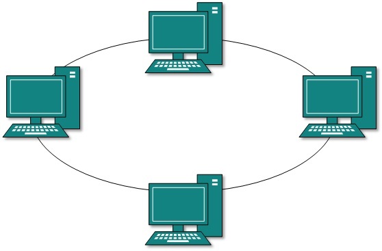
A ring network is a network topology in which each node connects to exactly two other nodes, forming a single continuous pathway for signals through each node - a ring. Data travel from node to node, with each node along the way handling every packet.
Rings can be unidirectional, with all traffic travelling either clockwise or anticlockwise around the ring, or bidirectional (as in SONET/SDH). Because a unidirectional ring topology provides only one pathway between any two nodes, unidirectional ring networks may be disrupted by the failure of a single link. A node failure or cable break might isolate every node attached to the ring. In response, some ring networks add a "counter-rotating ring" (C-Ring) to form a redundant topology: in the event of a break, data are wrapped back onto the complementary ring before reaching the end of the cable, maintaining a path to every node along the resulting C-Ring. Such "dual ring" networks include Spatial Reuse Protocol, Fiber Distributed Data Interface (FDDI), and Resilient Packet Ring. 802.5 networks - also known as IBM token ring networks - avoid the weakness of a ring topology altogether: they actually use a star topology at the physical layer and a media access unit (MAU) to imitate a ring at the datalink layer.
Some SONET/SDH rings have two sets of bidirectional links between nodes. This allows maintenance or failures at multiple points of the ring usually without loss of the primary traffic on the outer ring by switching the traffic onto the inner ring past the failure points.
Advantages
See also: Ring Protection
- Very orderly network where every device has access to the token and the opportunity to transmit
- Performs better than a bus topology under heavy network load
- Does not require a central node to manage the connectivity between the computers
- Due to the point to point line configuration of devices with a device on either side (each device is connected to its immediate neighbor), it is quite easy to install and reconfigure since adding or removing a device requires moving just two connections.
- Point to point line configuration makes it easy to identify and isolate faults.
- reconfiguration for line faults of bidirectional rings can be very fast, as switching happens at a high level, and thus the traffic does not require individual rerouting
Disadvantages
- One malfunctioning workstation can create problems for the entire network. This can be solved by using a dual ring or a switch that closes off the break.
- Moving, adding and changing the devices can affect the network
- Communication delay is directly proportional to number of nodes in the network
- Bandwidth is shared on all links between devices
- More difficult to configure than a Star: node adjunction = Ring shutdown and reconfiguration
Misconceptions
- "Token Ring is an example of a ring topology." 802.5 (Token Ring) networks do not use a ring topology at layer 1. As explained above, IBM Token Ring (802.5) networks imitate a ring at layer 2 but use a physical star at layer 1.
- "Rings prevent collisions." The term "ring" only refers to the layout of the cables. It is true that there are no collisions on an IBM Token Ring, but this is because of the layer 2 Media Access Control method, not the physical topology (which again is a star, not a ring.) Token passing, not rings, prevent collisions.
- "Token passing happens on rings." Token passing is a way of managing access to the cable, implemented at the MAC sublayer of layer 2. Ring topology is the cable layout at layer one. It is possible to do token passing on a bus (802.4) a star (802.5) or a ring (FDDI). Token passing is not restricted to rings.
Saturday, 4 July 2015
Windows Store apps
Windows Store apps

Alongside Office RT, free versions of OneNote and the Lync client were made available as Windows Store apps upon the release of Windows 8 and RT. The OneNote app, originally known as OneNote MX, contains a limited feature set in comparison to its desktop version, but is also optimized for use on tablets. The OneNote app has since received several major updates, including camera integration, printing abilities, and multiple inking options.
Universal Microsoft Word, Excel, and PowerPoint apps for Windows 10 are in the preview stage and are set for release later in 2015.
Office Mobile
Further information: Microsoft Office Mobile
Windows Phone 8 ships with an updated version of the Office Mobile suite, consisting of mobile versions of Word, Excel, PowerPoint, and OneNote. In comparison to their Windows Phone 7 versions, the new versions add an improved Office Hub interface that can sync recently opened and modified documents (including changes to documents stored via Office 365 and SkyDrive), a separated OneNote app with additional features (such as voice notes and integration with the new "Rooms" functionality of the OS), and improved document editing and viewing functionality.
In June 2013, Microsoft released a version of Office Mobile for iPhone; it is similar to the Windows Phone version, but originally requires an Office 365 subscription to use. A version for Android smartphones was released in July 2013; it, too, originally needed Office 365 for use.
Apps for iPad and Android tablet computers were released in March 2014 and January 2015, respectively These, along with their smartphone equivalents, have been made free for personal use, though certain premium features have been paywalled and require Office 365, which includes licensing of the apps for business use.
Windows 10 Mobile, set for release later in 2015, will come with brand new Office apps, more in line with their iPhone and Android equivalent, and making use of the "universal app" platform pioneered with Windows 10.
Comparison
| As an individual product | Traditional editions | Office 365 subscriptions[46][67] | |||||||||||
|---|---|---|---|---|---|---|---|---|---|---|---|---|---|
| Office RT | Home & Student | Home & Business | Standard | Professional | Professional Plus | Personal[68] | Home | University[69] | Small Business Premium | ProPlus | Enterprise | ||
| Availability | Varies | Windows RT | Retail,OEM | Retail,OEM | Volume licensing | Retail, OEM | Volume licensing | Software plus services | Software plus services | Software plus services | Software plus services | Software plus services | Software plus services |
| Maximum users | 1 | 1 | 1 | 1 | As licensed | 1 | As licensed | 1 | all users in one household[70] | 1 | 10 | 25[71] | Unlimited |
| Devices per user | 1 | 1 | 1 | 1 | As licensed | 1 | As licensed | 1 computer and 1 mobile | 5 shared among all users[70] | 2 computers and 2 mobiles | 5 | 5[71] | 5 |
| Commercial use allowed? | Yes | Separate2 | No | Yes | Yes | Yes | Yes | No | No[72] | No | Yes | Yes | Yes |
| Word | Yes | Yes1 | Yes | Yes | Yes | Yes | Yes | Yes | Yes | Yes | Yes | Yes | Yes |
| Excel | Yes | Yes1 | Yes | Yes | Yes | Yes | Yes | Yes | Yes | Yes | Yes | Yes | Yes |
| PowerPoint | Yes | Yes1 | Yes | Yes | Yes | Yes | Yes | Yes | Yes | Yes | Yes | Yes | Yes |
| OneNote | Yes3 | Yes1 | Yes | Yes | Yes | Yes | Yes | Yes | Yes | Yes | Yes | Yes | Yes |
| Outlook | Yes | Yes1 | No | Yes | Yes | Yes | Yes | Yes | Yes | Yes | Yes | Yes | Yes |
| Publisher | Yes | No | No | No | Yes | Yes | Yes | Yes | Yes | Yes | Yes | Yes | Yes |
| Access | Yes | No | No | No | No | Yes | Yes | Yes | Yes | Yes | Yes | Yes | Yes |
| InfoPath | No | No | No | No | No | No | Yes | No | No | No | No4 | Yes | Yes |
| Lync | Yes3 | No | No | No | No | No | Yes | No | No | No | Yes | Yes | Yes |
| SharePoint Designer | Yes | No | No | No | No | No | No | No | No | No | No | No | No |
| Project Has multiple editions | Yes | No | No | No | No | No | No | No | No | No | No | No | No |
| Visio Has multiple editions | Yes | No | Viewer | Viewer | Viewer | Viewer | Viewer | Viewer | Viewer | Viewer | Viewer | Viewer | Viewer |
- Remarks
- 1 The Windows RT versions do not include all of the functionality provided by other versions of Office.
- 2 Commercial use of Office RT is allowed through volume licensing or business subscriptions to Office 365.
- 3 Windows Store versions are also available.
- 4 InfoPath was initially part of Office 365 Small Business Premium. However, it no longer is.
System requirements
Each Microsoft Office 2013 application has the following requirements, although there may be app-specific requirements.
| Item | Requirement |
|---|---|
| CPU | 1 GHz clock speed, IA-32 or x64 architecture with SSE2 support |
| RAM | IA-32 edition: 1 GB x64 edition: 2 GB |
| Hard disk drive | 3.0 GB free disk space |
| Operating system |
|
| Software | .NET Framework 3.5, 4.0 or 4.5 |
In addition to these, graphics hardware acceleration requires a screen resolution of 1024×576 pixels or larger and a DirectX 10-compliant GPU with at least 64 MB of video memory (in case of absence of the required hardware, however, Office 2013 applications can still run without graphics acceleration.)
Subscribe to:
Posts (Atom)
